We started off gaining knowledge from an open design platform and progressed through using the internet to source information as well as simple trial and error. Everything i’ve done to make this design is free to access on the internet on sites that allow free membership (WordPress and Instructables).
I think this iteration it’s a really simple starting point and there are definitely a lot of things anyone could further develop on this concept: the fabric properties, defining the minutes with embroidery as i researched, more intricate coding, etc.
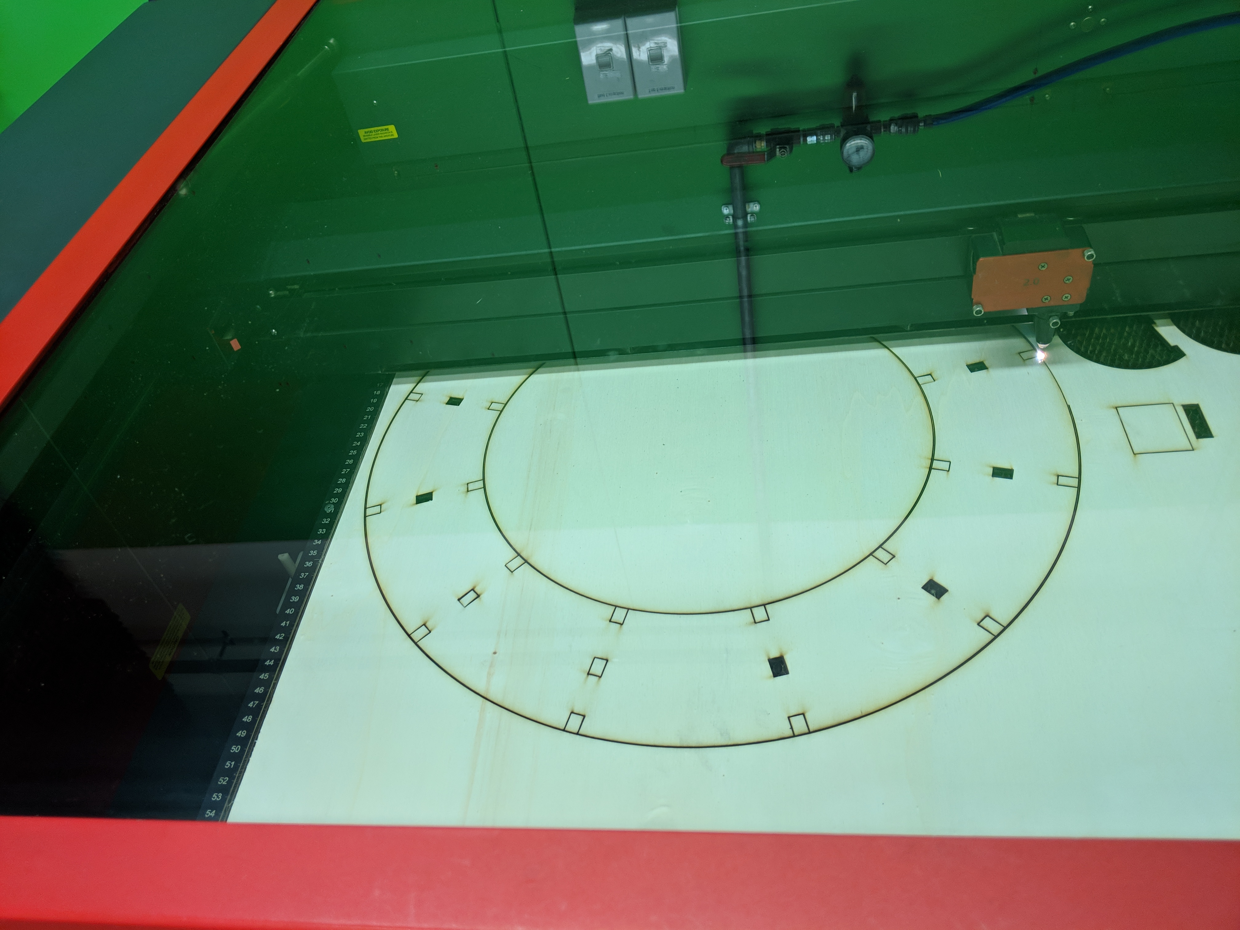
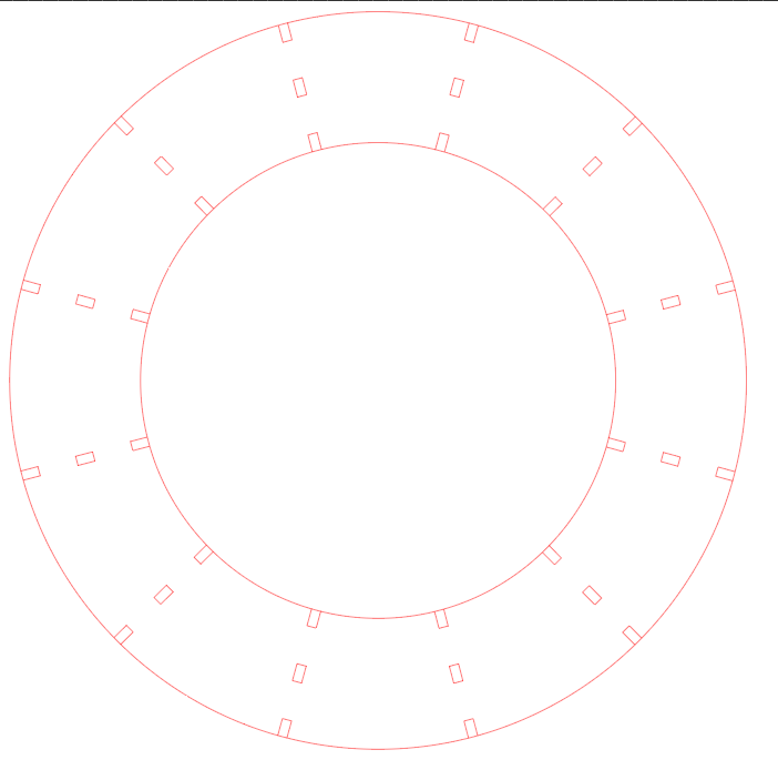
You can pay for access to a laser cutter and all of my files are condensed so material is minimised.
Thanks to…
Fab lab Wellington fablabwgtn.co.nz All my gifs were made using giphy.com Massey University COCA
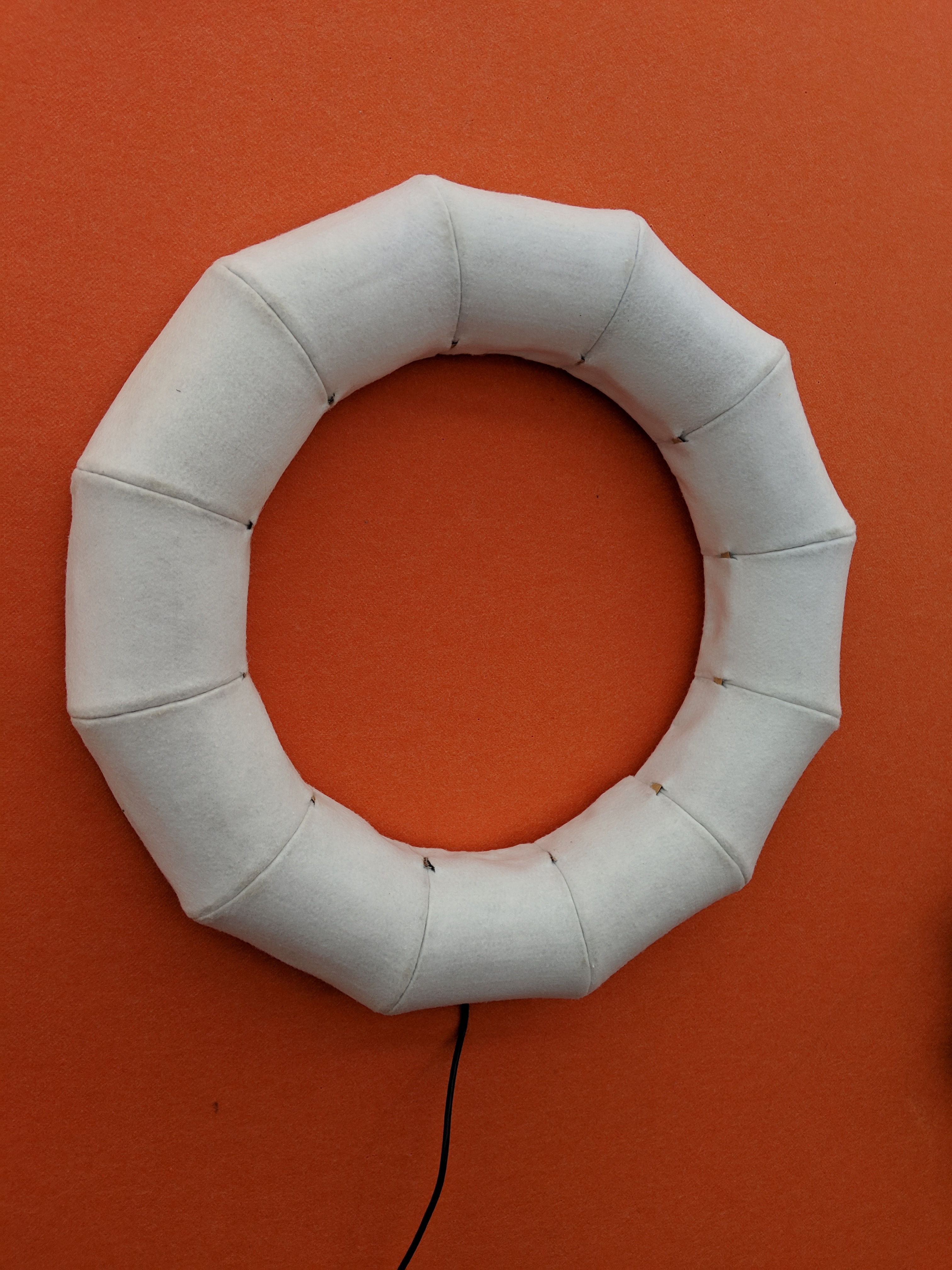
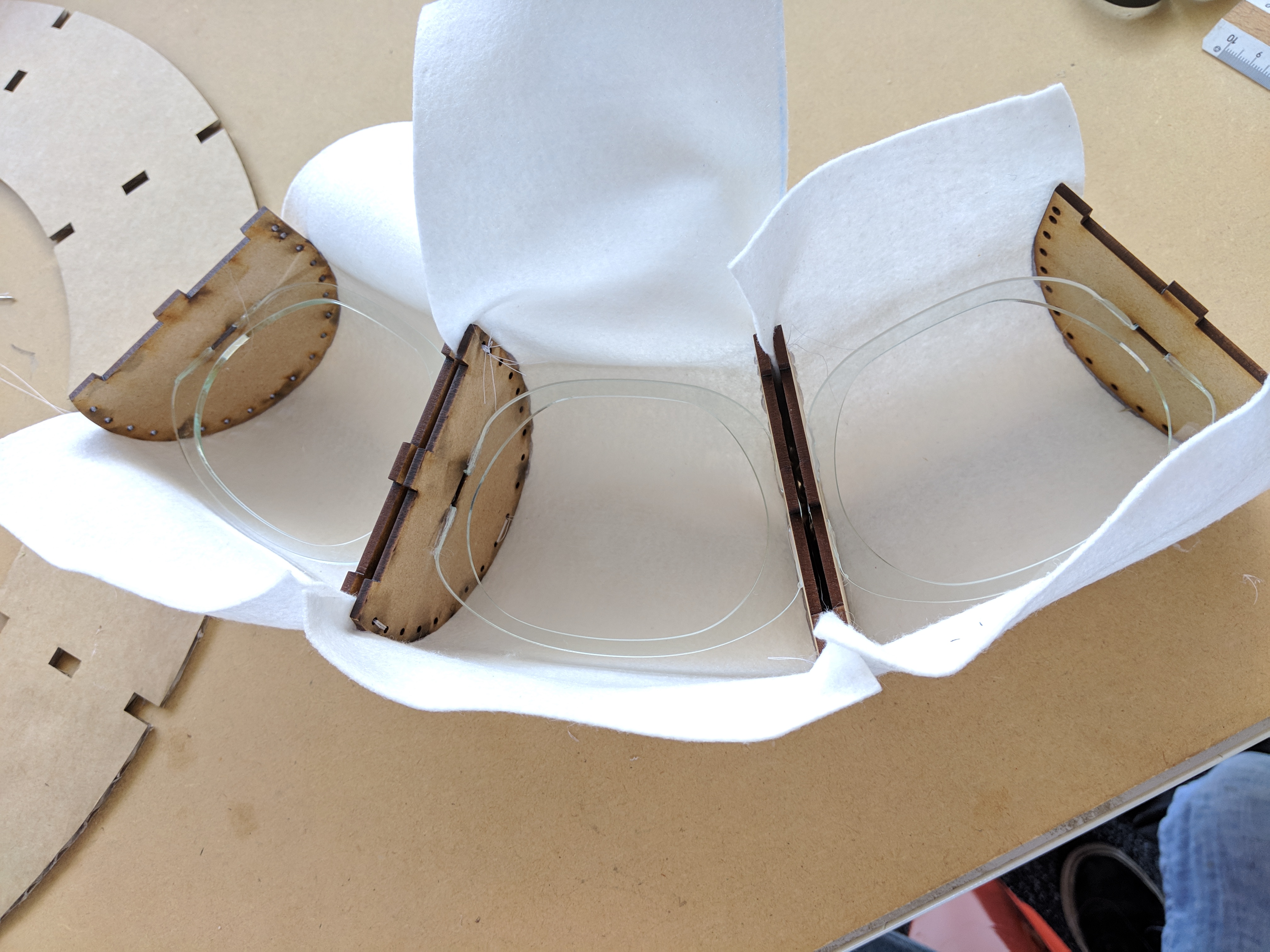
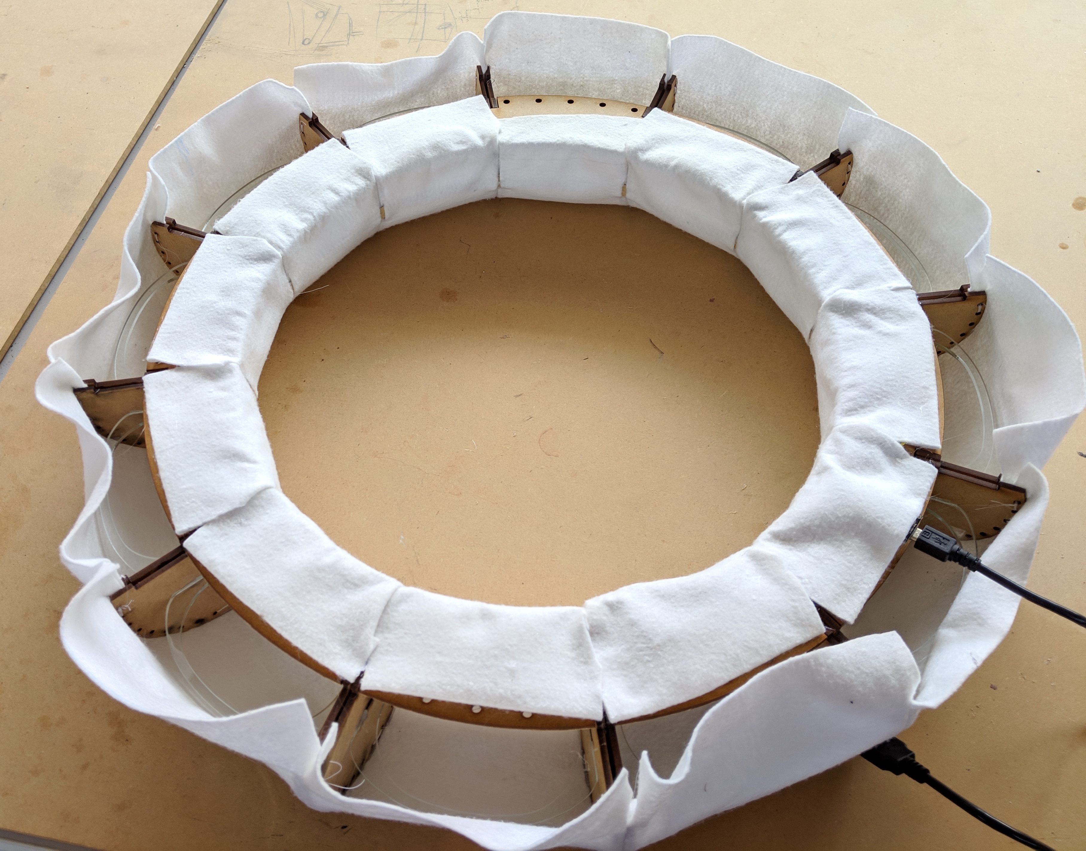
Decided on felt as my final material. Cut the spacing pieces from clear acrylic , hoping the light will shine through
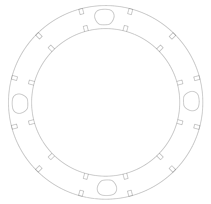
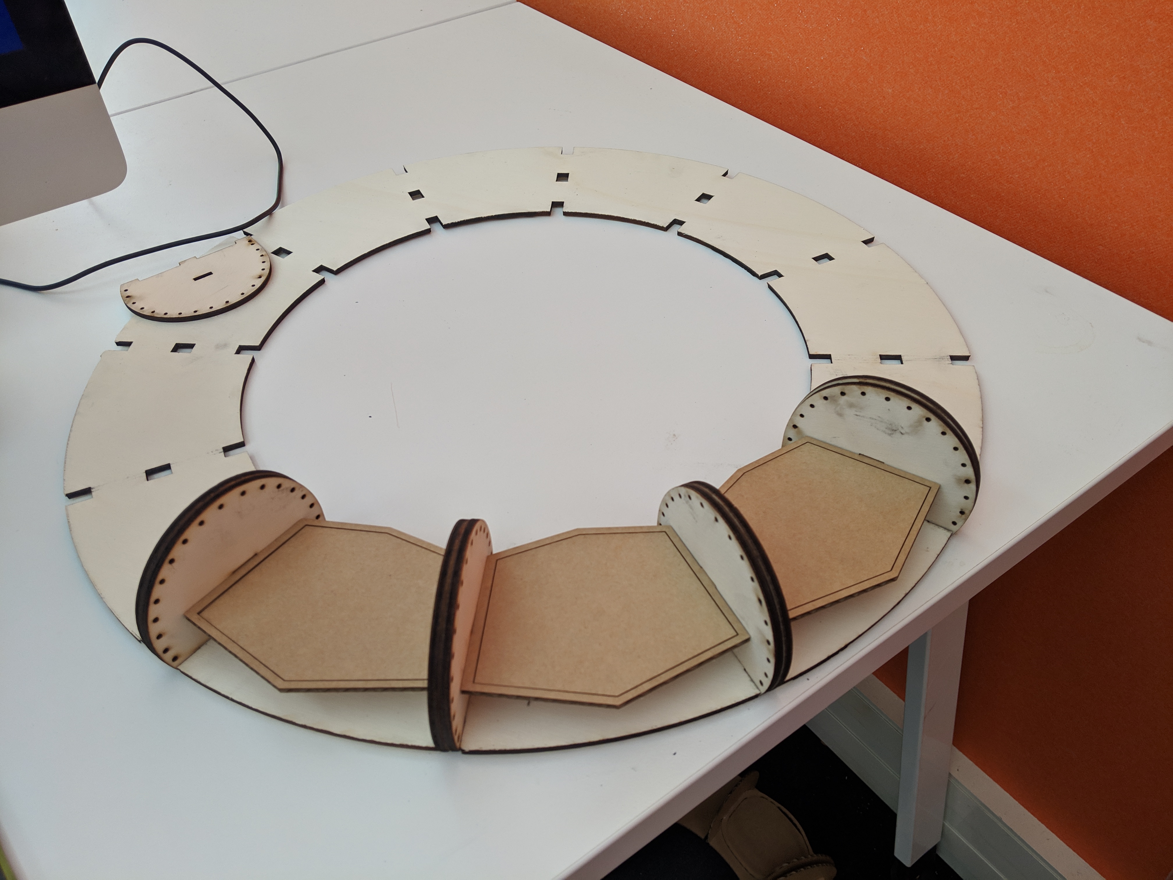
Because we are not allowed to cut MDF on the laser cutter in the Fab lab and the original design for the back of the clock would’ve been too big for any laser cutters in the 3D workshop I had to alter the design slightly. To problem solve I dedcided to make the back of the clock from seperate pieces. Here is the inner piece. It has a cut-out every third section that will allow me to push the fabric back into place later, should it become dented or sunken.
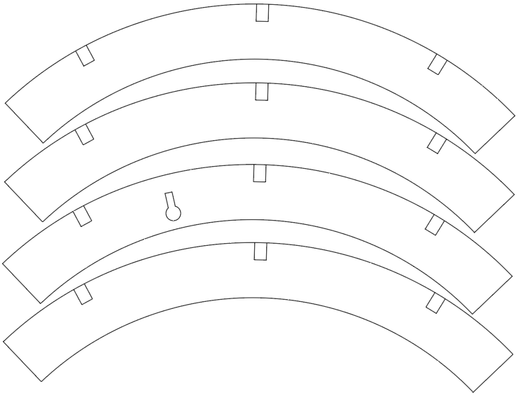
These piececs make up the outer section of the back of the clock. The lock shaped cutout enables the clock to be hung on the wall with a drawing pin.
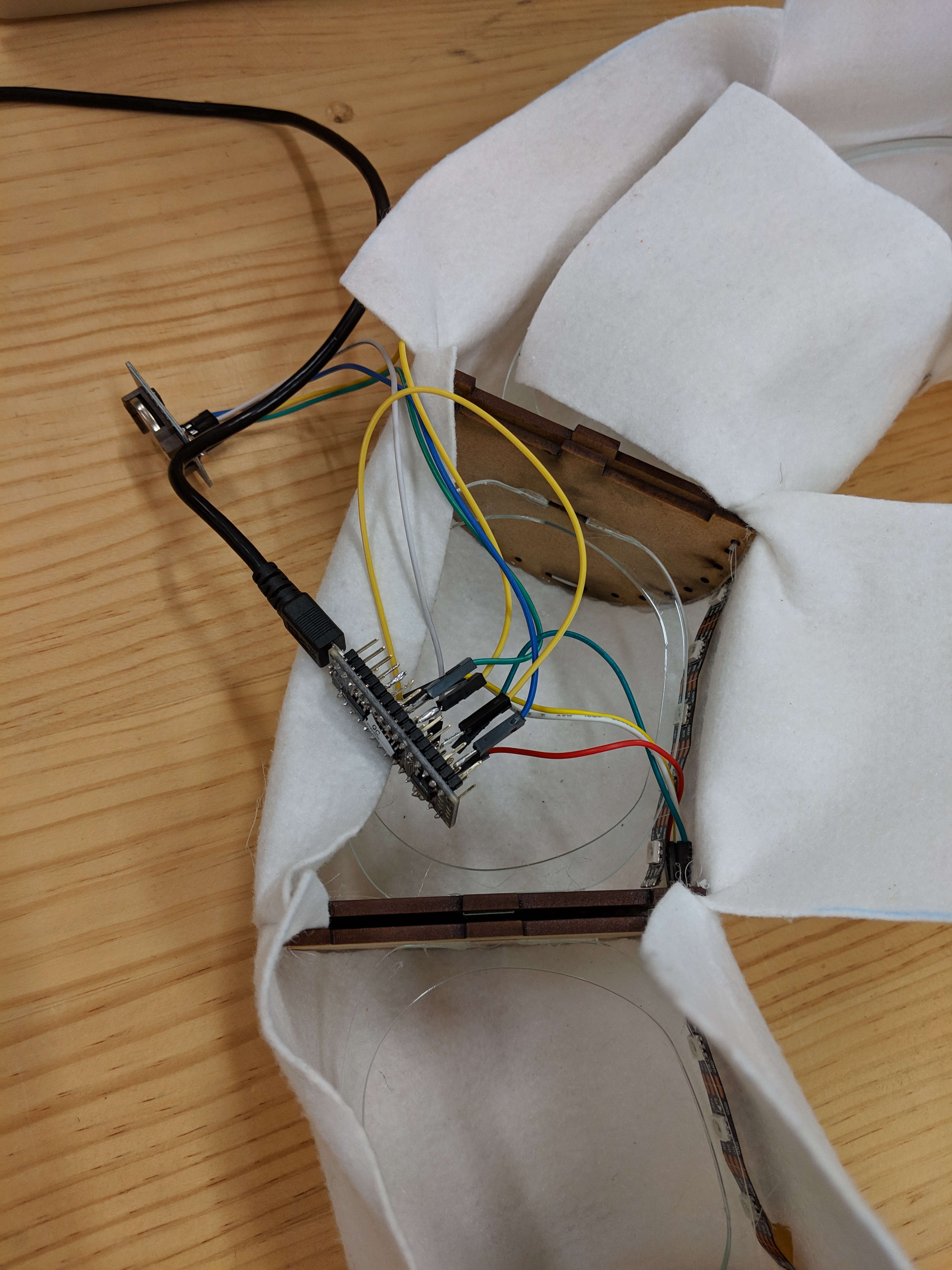
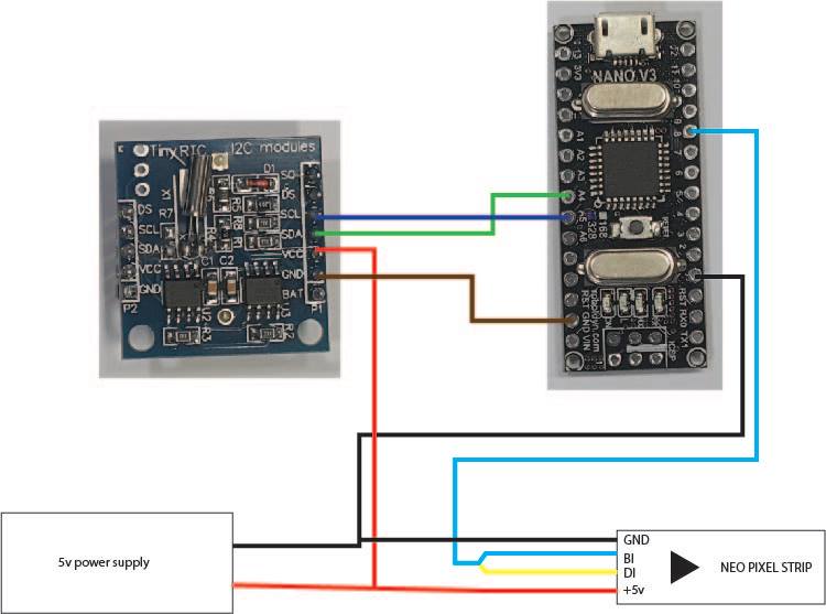
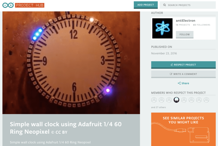
Soldering this was SO fiddly. I used the diagram in my ‘wiring up’ blog post as guidance as well as some information from: https://create.arduino.cc/projecthub/mitov/arduino-nano-ds1307-real-time-clock-rtc-with-visuino-572ad8. This is because after talking with Harry about cordless power sources / battery options I realised that to supply the Arduino with the 5V it needs – no more no less – I would need to purchase a voltage converter.
I would’ve liked to refine the design more especially in regards to the back of the clock to make it a more complete product but luckily it does not affect the appearance when in use.
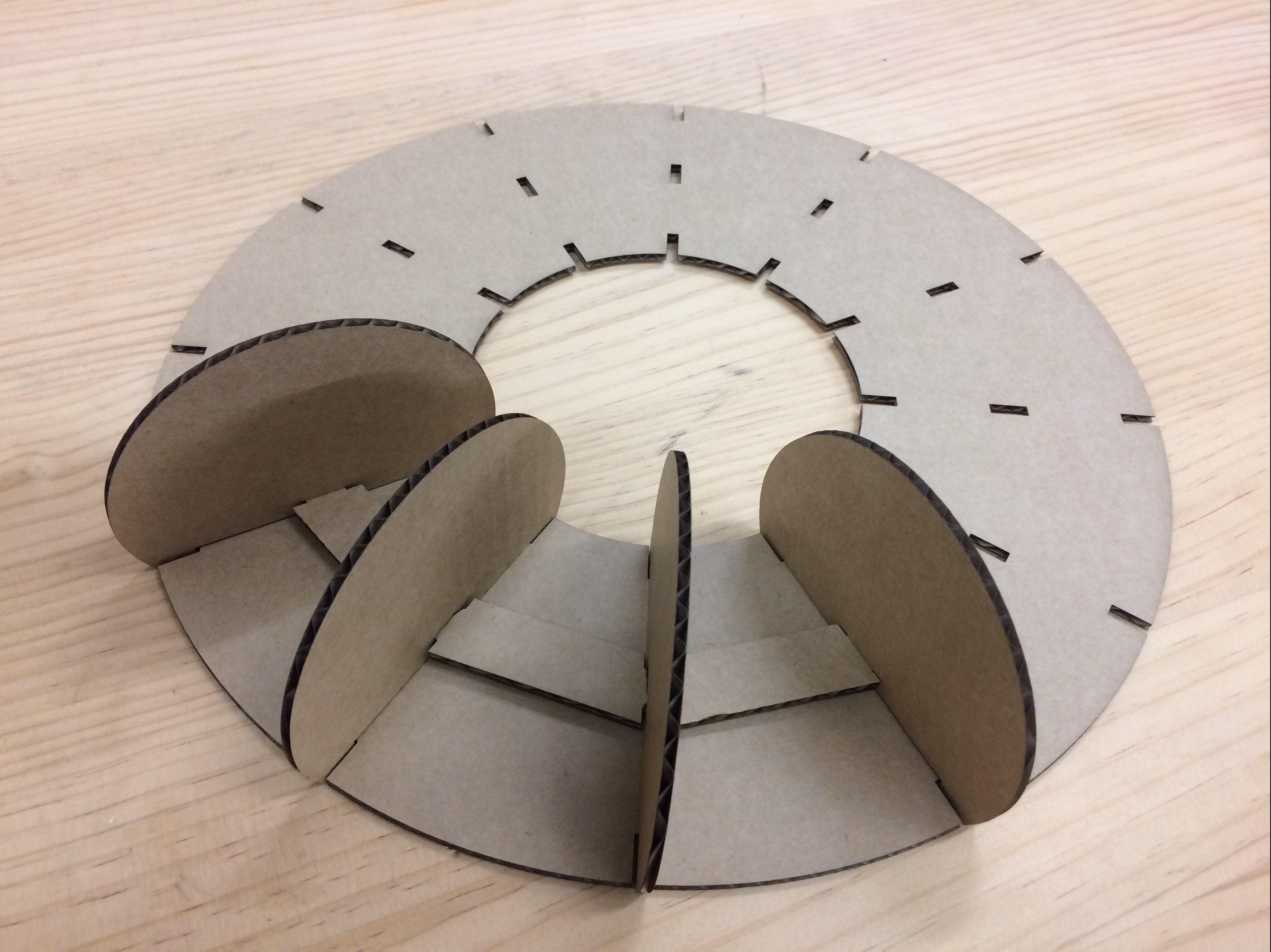
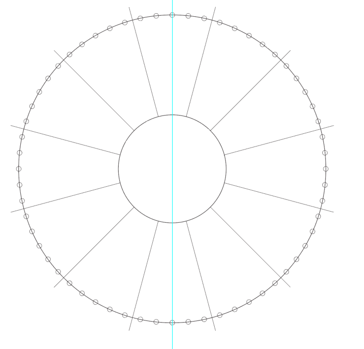
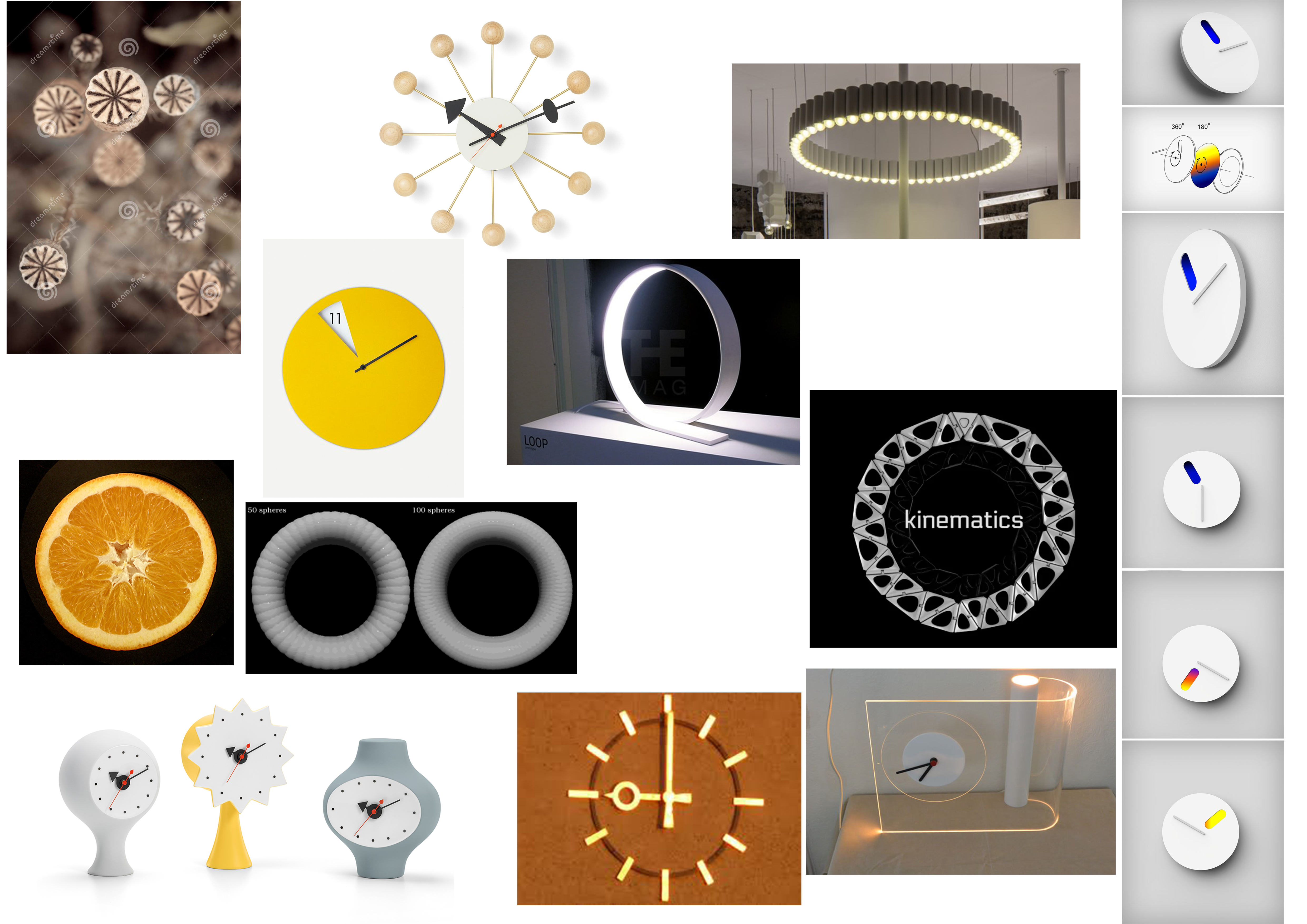
This was my first prototype. I created a simple illustrator file with measurements for the neopixel strip to fit around the outer circumference, with the light shining inwards. My laser cut on cardboard went well and the pieces fit together but the size in person seemed too small and I would rather the light shone outwards.
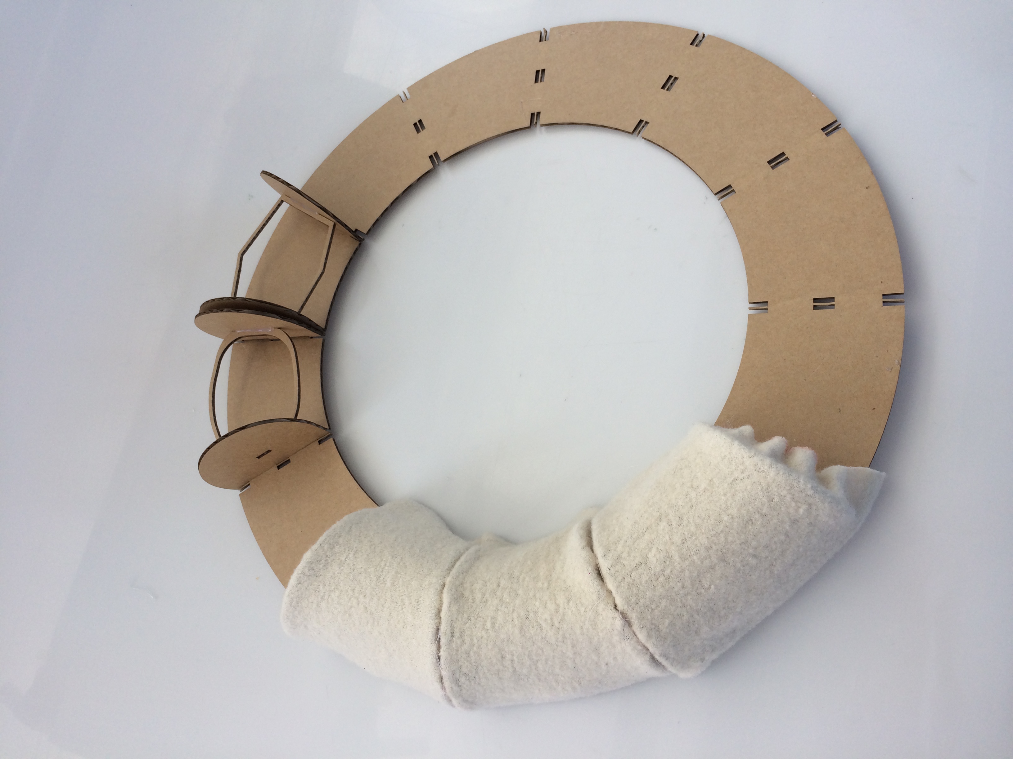
I then changed the measurements of the illustrator file to have the Neopixel strip running along the inside circumference and the light shining outwards. This size worked a lot better visually. Another iteration I made was to shorten the segmenting pieces so that the profile of the clock won’t be as tall but light will show up brighter / not as diffused. To test out how fabric would sit on the form I made a basic paper stencil as Emma suggested and adhered fabric off an old dressing-gown over each section..
Some further iterations included getting rid of the small gap between the slot holes on the back piece that fit the segmenting pieces, and adding holes to the design of these pieces so that the fabric could be sewn onto them and the pieces could be sewn together rather than glued. I thought poplar ply would be a good choice as a final material and used it for this prototype, however, it was very ashy on the edges that had been laser cut as you can see in the pictures above. Now I have decided to use MDF as my final material because acrylic was only available in transparent colours.
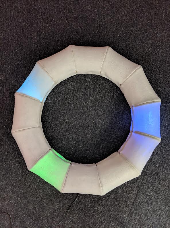
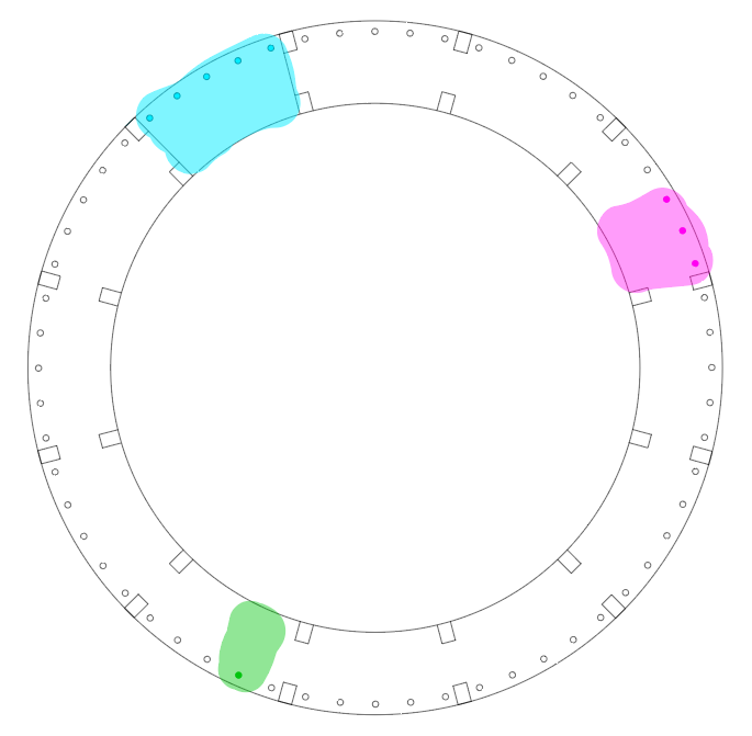
Plan: Seconds colour duller and matching clock body. Hours and minutes bright white.. Hours 2 leds, mins 1?
I played around a bit with the code after class and wit some help from Wendy, managed to change the colour and brightness of the LEDs. As well as this I made the hour representative LEDs 5 instead of the original code’s 3, and the minutes into 3 LEDs.
Below is my edited code.
LIZZIE_LOVES_CODE_mick:
#include <Wire.h>
#include <RTClib.h>
#include <Adafruit_NeoPixel.h>


#define PIN 8
#define PIXEL 60


Adafruit_NeoPixel strip = Adafruit_NeoPixel(60, PIN, NEO_GRB + NEO_KHZ800); // wrote 60 where PIXEL was


//DS1307 RTC;// D103248237124 Establish clock object

RTC_Millis RTC;

DateTime Clock; // Holds current clock time

byte hourval, minuteval, secondval;


void setup() {
   strip.begin();
  strip.show(); // Initialize all pixels to 'off' //added this and above line
  Serial.begin(9600);
  Wire.begin();          // Begin I2C
  RTC.begin();   // begin clock


  if (! RTC.isrunning()) {
    //  Serial.println("RTC is NOT running!");
    // following line sets the RTC to the date & time this sketch was compiled

  }

    RTC.adjust(DateTime(__DATE__, __TIME__));
  strip.begin();
  strip.show(); // Initialize all pixels to 'off'
  strip.setBrightness(255); // max is 255

}


void loop() {


  Clock = RTC.now(); // get the RTC time

  secondval = Clock.second();  // get seconds
  minuteval = Clock.minute();  // get minutes
  hourval = Clock.hour();   // get hours


  if (hourval > 11) hourval -= 12; // This clock is 12 hour, if 13-23, convert to 0-11
  hourval = (hourval * 60 + minuteval) / 12;

  strip.setPixelColor(hourval, 0x008080, 51, 255, 255); strip.setPixelColor(hourval - 1, 0x004040, 51, 255, 255); strip.setPixelColor(hourval - 2, 0x004040, 51, 255, 255); strip.setPixelColor
  (hourval - 3, 0x004040, 50, 255, 255); strip.setPixelColor(hourval - 4, 0x004040, 51, 255, 255);
  // I added another strip of positioning code to the line above to add 2 more pixels either side making 5.
  //    strip.setPixelColor(hourval-2, 0x001010);strip.setPixelColor(hourval+2, 0x001010);
  strip.setPixelColor(minuteval, 0x800080, 255,0,0); strip.setPixelColor(minuteval - 1, 0x000000, 255,0,0); strip.setPixelColor(minuteval + 1, 0x000000, 255,0,0);
  //    strip.setPixelColor(minuteval-1, 0x200020);strip.setPixelColor(minuteval+1, 0x200020);
  strip.setPixelColor(secondval, 0x808000, 255, 255, 255);//strip.setPixelColor(secondval-1, 0x002F00);strip.setPixelColor(secondval+1, 0x002F00);
  strip.show();

  strip.setPixelColor(hourval, 0x000000); strip.setPixelColor(hourval - 1, 0x000000); strip.setPixelColor(hourval + 1, 0x000000);
  //added +2 -2 to this line also
  strip.setPixelColor(hourval - 2, 0x000000); strip.setPixelColor(hourval + 2, 0x000000);
  strip.setPixelColor(minuteval, 0x000000); strip.setPixelColor(minuteval - 1, 0x000000); strip.setPixelColor(minuteval + 1, 0x000000);
  strip.setPixelColor(secondval, 0x000000);//strip.setPixelColor(secondval-1, 0x000000);strip.setPixelColor(secondval+1, 0x000000);

  delay(25);


     Serial.print(hourval, DEC);
     Serial.print(':');
    Serial.print(minuteval, DEC);
     Serial.print(':');
     Serial.println(secondval, DEC);


}
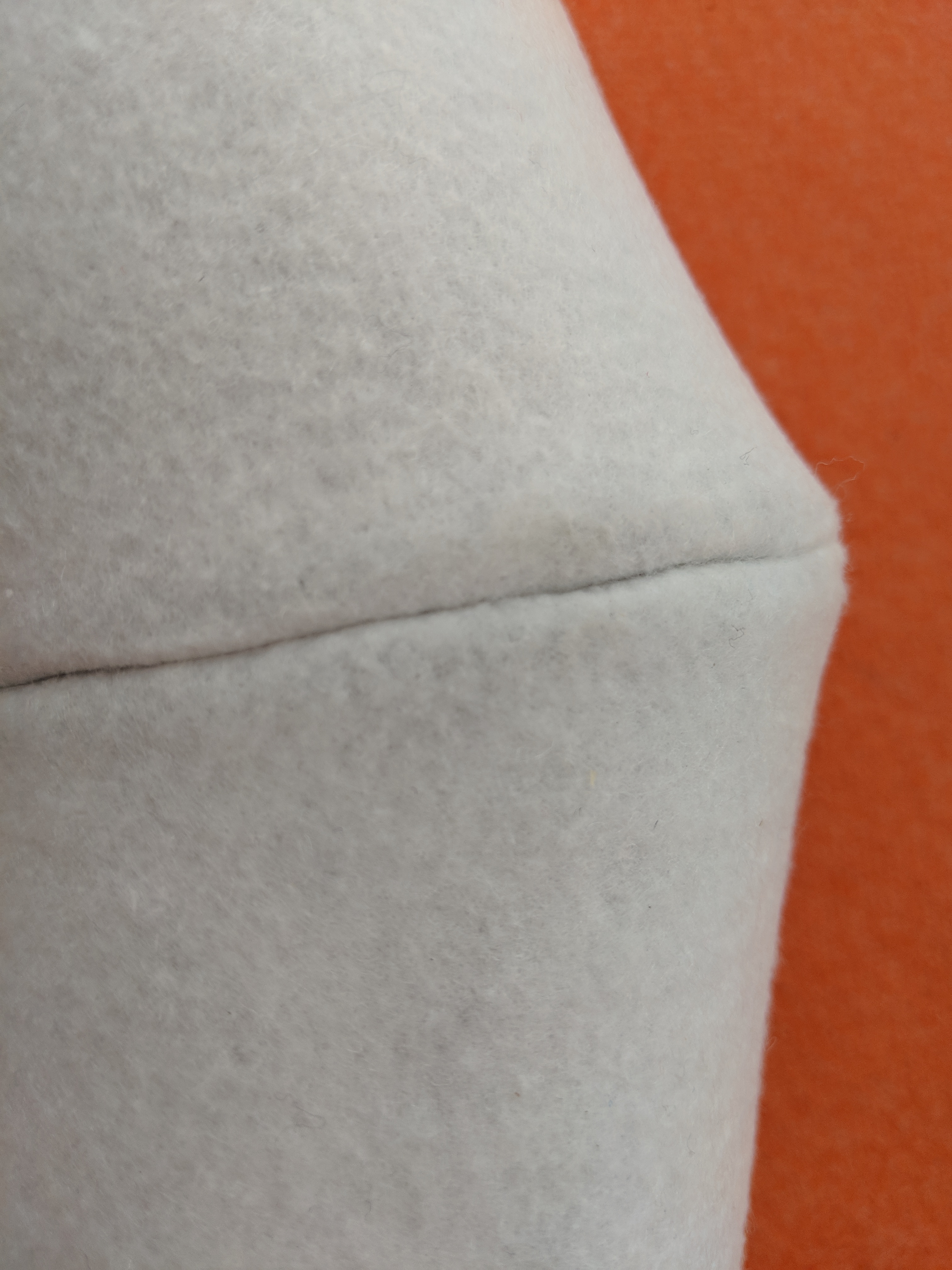
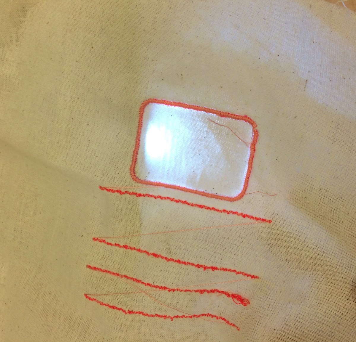
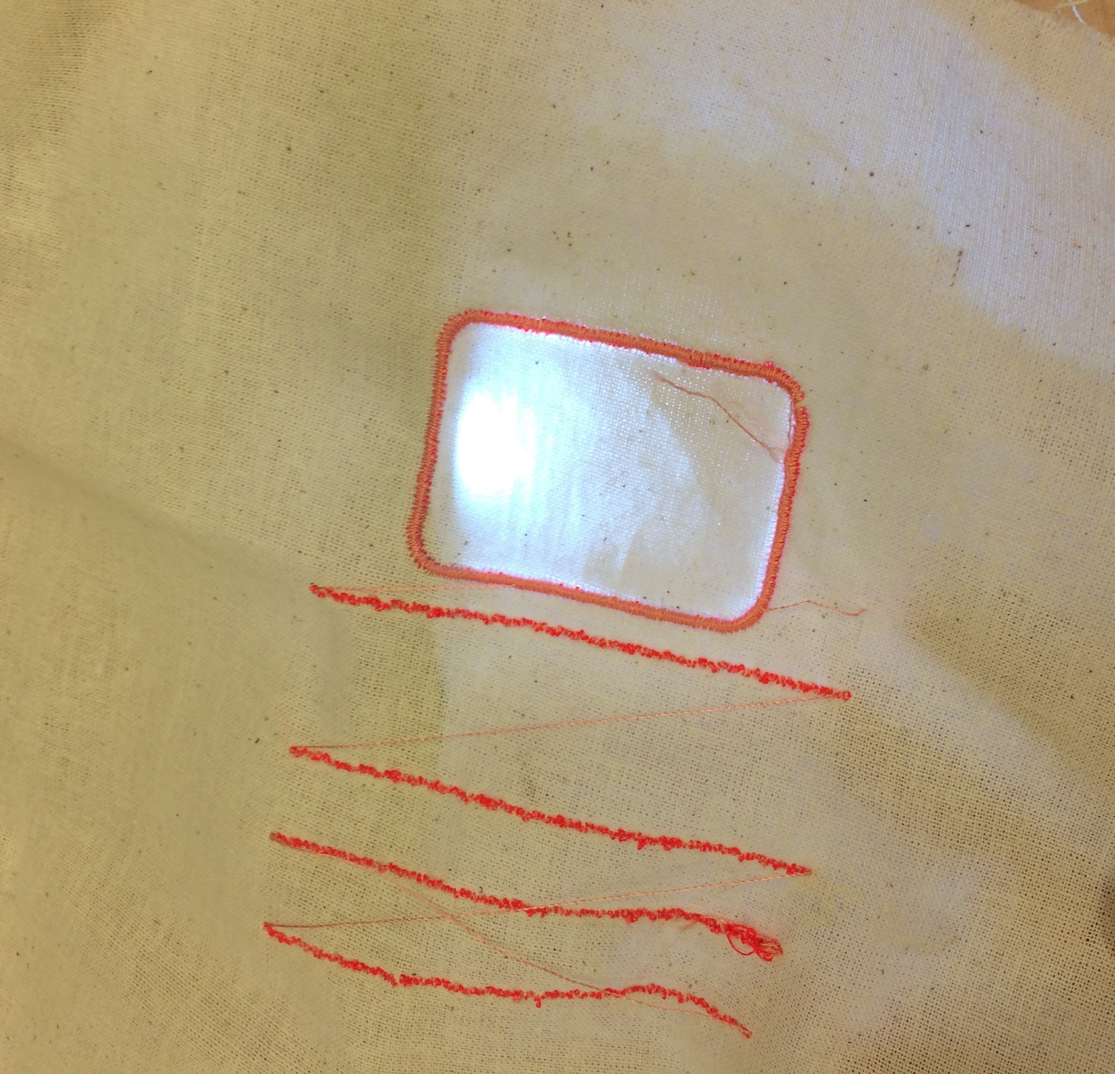
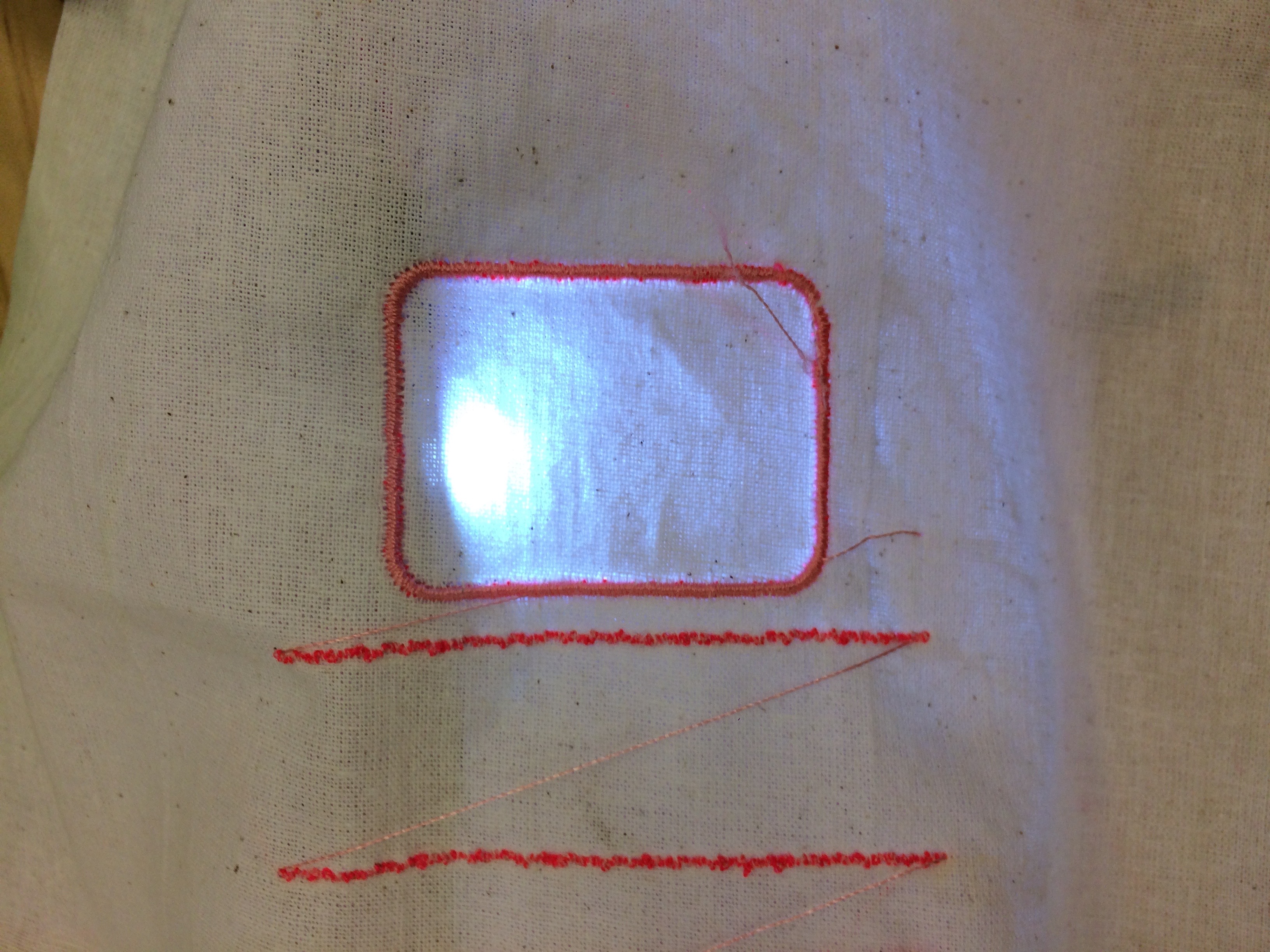
I would like to use digital embroidery to create the ‘minute lines’ on my clock, so as the LEDS representing minutes move around the clock it is easier to gauge the exact time.
The embroidery seems to focus the light between the lines. It shines brightly next to the stitches where the needle had poked holes.
Yesterday we unpacked our Arduino Nano knock offs and RTC’s.
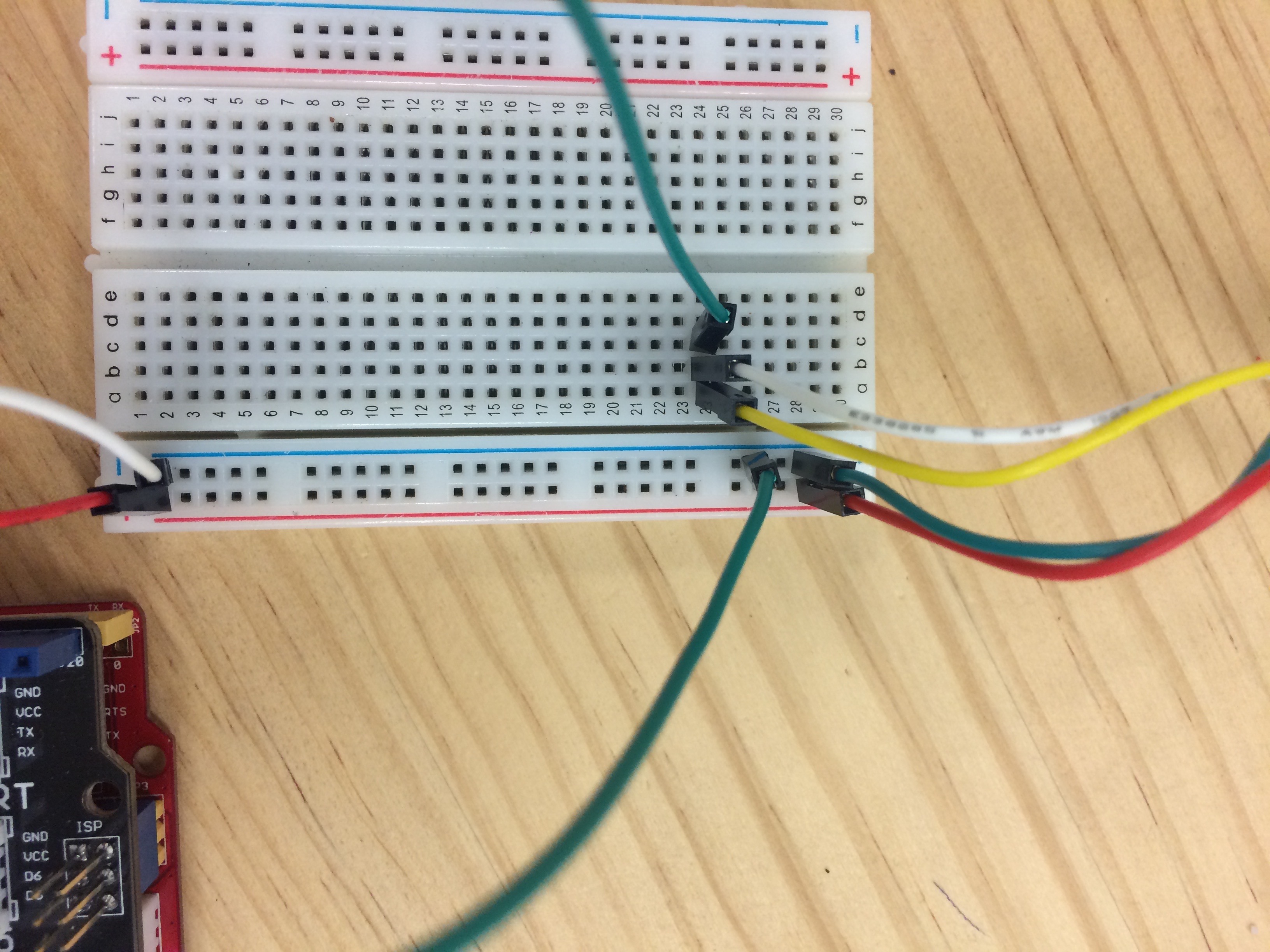
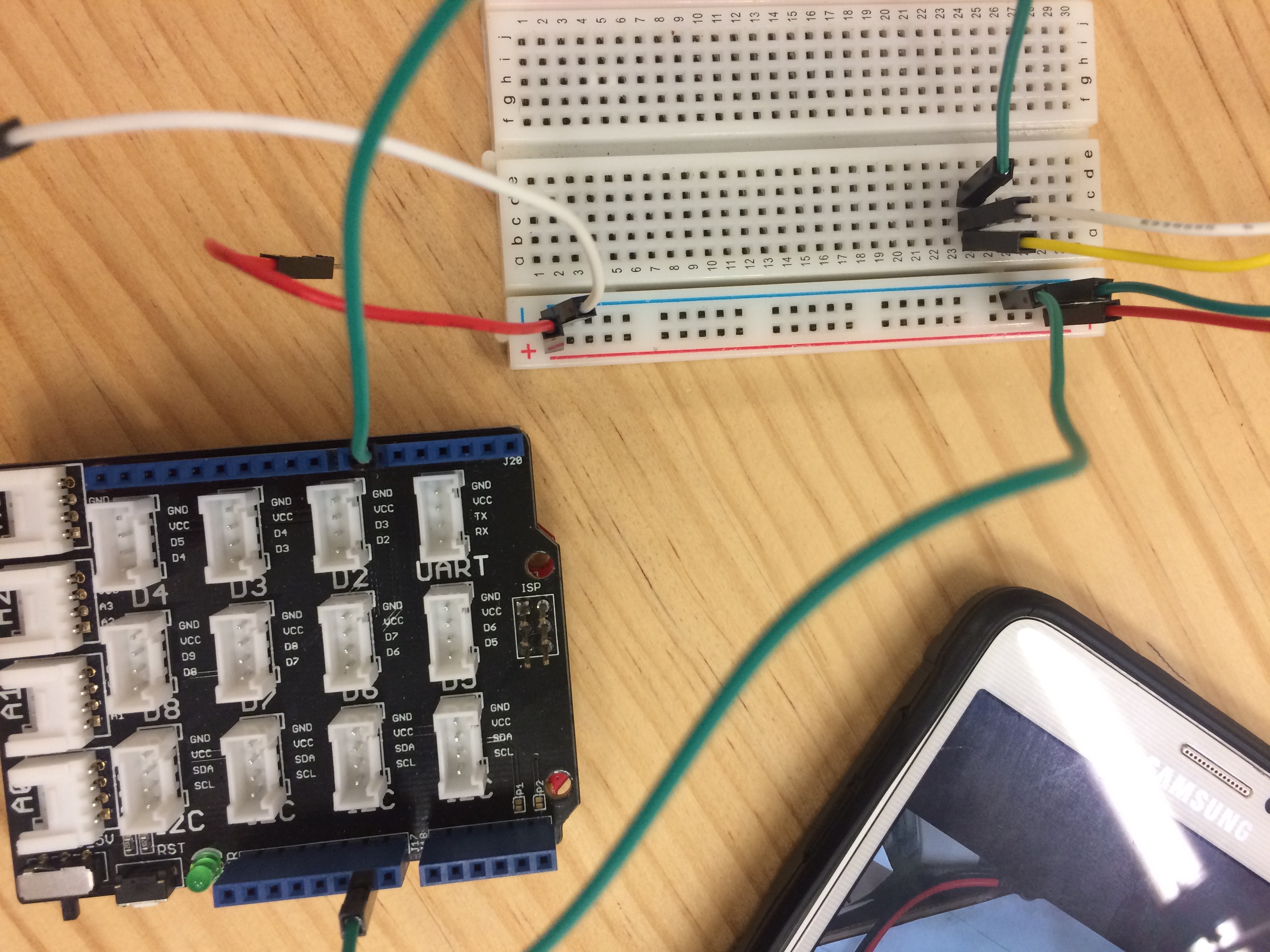
After struggling with our code for too long Keiran and I went to Massey music department and got some advice from a friendly masters student who also helped us solder on the legs of our Arduinos so that we could wire them up easier using a bread board (she explained to us how this worked as well. We wired the Arduino and RTC together following the instructables post below: https://www.instructables.com/id/Arduino-Nano-DS1307-Real-Time-ClockRTC-With-Visuin/
I have previously used laser cutters and 3D printers, however, Wendy gives some very handy advice on FabLab’s digital fabrication machines. I will document the most useful for myself here:
Laser cutter
Download the templates for all laser cutters. Efficient design practice.
They use vector based software (illustrator).
Rocket ship symbol , enhance thin lines.
Rasterising is horizontal so flipping things
3D printer
Layer height must be multiple of nozzle size as well as width???
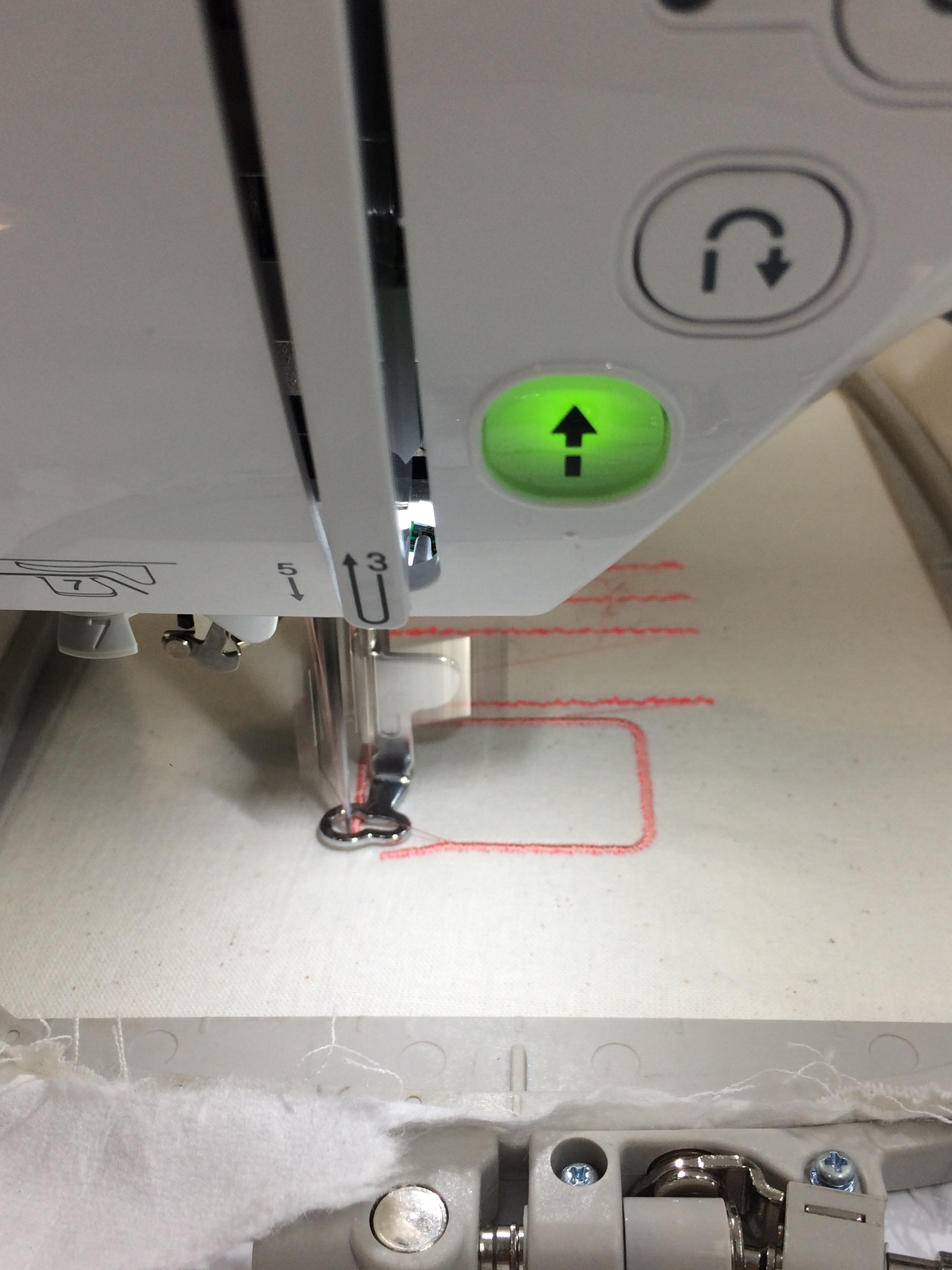
Digital Embroidery
Load com with ubuntu. Click Ubuntu again. Ubuntu is vector based.
Load Inkscape.
Fabric held in plastic embroidery hoops. Inkscape page size needs to be size of one of the embroidery hoops (written on frame of hoops).
Fill and stroke settings. Select square w paintbrush icon above T. Choose any dashes other than straight line. Won’t affect what it looks like on machine. No fill w dashed line = running stitch.
Blak line = zigzag. also no fill. Adjust width to what u want (mm).
To fill= Select fill. Will outline fill if u select a stroke. Untick for normal fill.
Export by = extentions – inkstitch -params. Assign each object some parameters. (or previous extention settings.
Params – repeat should default to 1. Default 1.5.
Apply will apply for the one obj. 0.4 is default for zigzag spacing.
for fill. Expand helps the fabric not be drawn together and therefore shrink. Max fill stitch length leave 3 prob. Spacing between rows changes lots.
Final step is to export file. Deselect all. extentions, inkstitch. eng. embroider. output file format is DST. file explorer then guest data folder. right click ur folder name then copy and paste in directory. Click live preview.
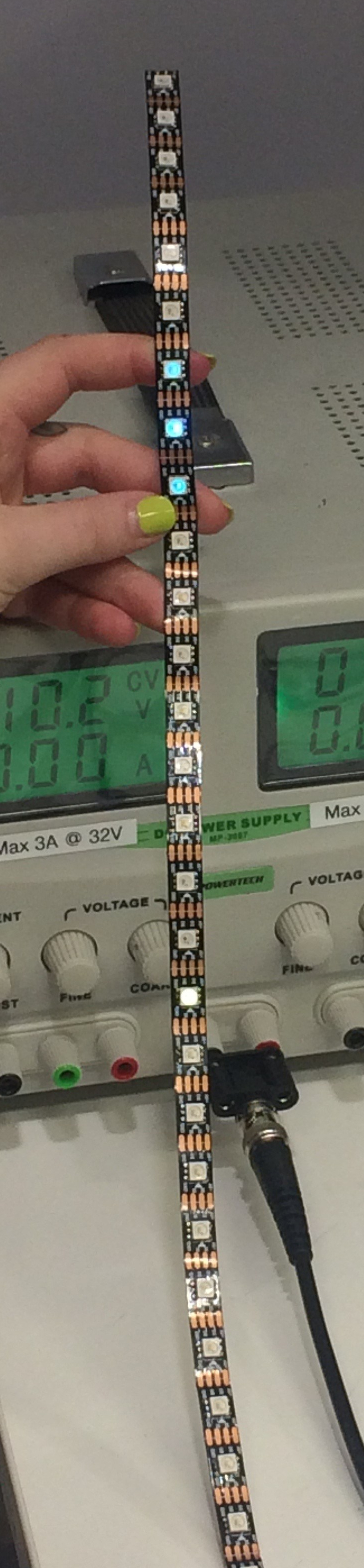
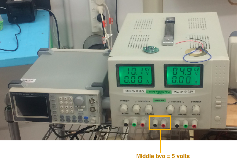
We are testing out more open sources codes using the long neopixel strip. This means we need an external power source because running too many LEDs through a USB port can cause it to blow up. The green display below must show below 5 volts (shows 4.9).
LED and Arduino run on 5 volts
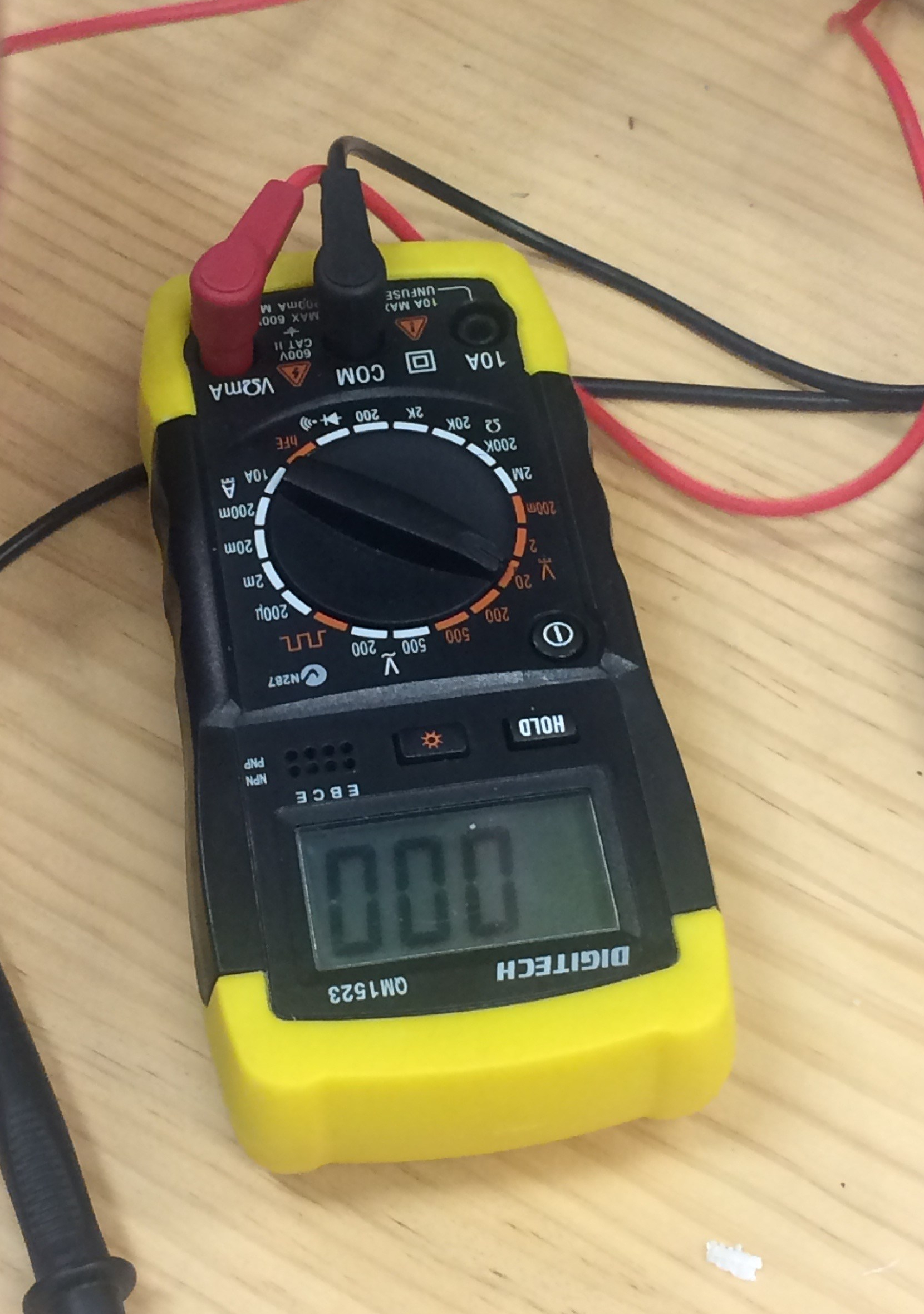
Multimeter:
Get the clip wires and make circuit -red to red, black to black.
– Set to 20v as 5 is lower than 20. – 5.1 is fine
When ready clip to circuit.
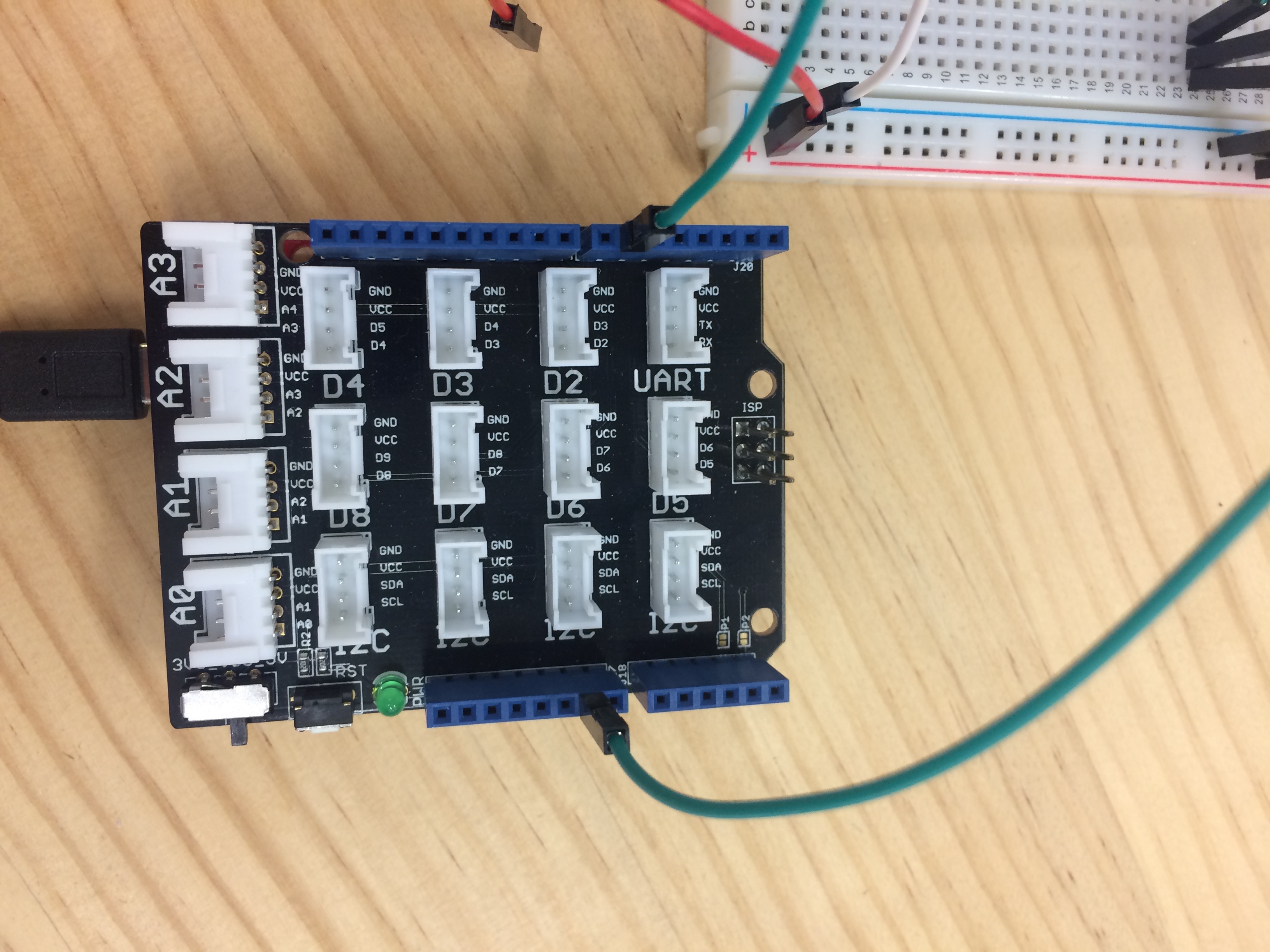
This is an important layout to remember when wiring up the external powers source: